Figure 1

Figure 2
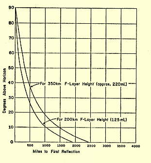
Figure 2 shows the ground distance covered by a signal transmitted at an angle of Ae. Denver is approximately 1025 miles from Los Angles. To travel a distance of 1025 miles, Figure 2 indicates that a single hop signal must be transmitted at an angle Ae = 18 degrees , and refract off the Ionosphere at an altitude of 220 miles, in order to return to Earth at Denver. If this transmission occurs at noon with a critical frequency of Fo = 9 MHz, then the maximum usable frequency for this transmission is Fm = Fo / (sin Ae) = 29.1 MHz. Thus communications with Denver under these conditions is possible all the way up to 10 meters. A double hop signal transmitted at an angle of 36 degrees can also be used to communicate from Los Angles to Denver. In this case, the transmitted signal will refract off the Ionosphere, return to Earth 512 miles from Los Angles, reflect from the Earth's surface, travel back up into the Ionosphere where it will be refracted a second time and finally arrive at Denver. The maximum usable frequency for this double hop path is Fm = 15.31 MHz assuming Fo = 9 MHz and Ae = 36 degrees . In this case, 20 meters is the highest usable amateur radio band for double hop communications between Los Angles and Denver. The single hop path will produce a stronger signal at Denver because it will incur lower losses than the double hop path. Using the information presented here, transmission to Denver via the single hop path can be guaranteed by using the 15, 12 or 10 meter bands. If 20 meters is used, signals may propagate to Denver via the single hop path, or the double hop path, or both. This could lead to undesirable multipath interference. Thus the best choice for communicating with Denver is to select one of the higher frequency bands that supports only the single hop propagation mode. At the same time, and under the same conditions, the maximum usable frequency for single hop communicating with San Diego (125 miles from Los Angles with a required elevation angle, shown in Figure 2, of Ae = 70 degrees) is Fm = 9.6 MHz. T hus the 40 meter band is the highest frequency amateur radio band capable of communicating between Los Angles and San Diego under these conditions.
Figure 2 shows that regional communications (communicating with stations located within 500 miles of the transmitting station) requires high transmission angles in the range from 35 degrees to 900. Regional HF communications is ideal for emergency communications work in which disaster relief organizations want to communicate with near by cities capable of sending personnel, equipment, and supplies to aid in the recovery efforts. Regional HF communications may be the only way of communicating with these cities during a natural disaster if they are beyond the reach of local VHF and UHF repeaters. DX communications, on the other hand, requires low transmission angles of 25 degrees or less to achieve transmission hops that are as long as possible.
Maximum usable angle is derived by solving the maximum usable frequency equation for A. Thus the maximum usable angle is equal to:
Am = sin-1[Fo / Fb]
In this equation, Fo is the critical frequency as before and varies throughout the day, seasonally, and in accordance with the 11 year solar cycle.
Fb is the center frequency of the particular amateur radio band that you are interested in.
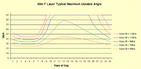
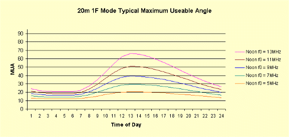
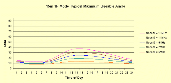
Am is the highest angle signal that can be transmitted from an antenna and return to Earth when operating in the fB frequency band with a critical frequency of Fo. Any signal transmitted at an angle less than Am will also be refracted back to Earth. However, transmitting at an angle greater than Am will result in the signal passing through the Ionosphere and being lost to outer space. Figures 3, 4, and 5 show curves for the maximum usable angle at noon time critical frequencies of Fo = 5 MHz (lowest curve), Fo = 7 MHz, Fo = 9 MHz, Fo = 11 MHz, and Fo= 13 MHz (highest curve), for the 40, 20, and 15 meter bands respectively.
Figure 3 clearly shows that 40 meters is an excellent regional communications band in that it supports high transmission angles a good portion of the time. Potentially 40 meters is also a good DX band since it also supports low angle transmissions (transmissions at all angles less than the maximum usable angles shown in the chart). However, during day light hours the Ionosphere D Layer absorbs low angle 40 meter signals minimizing 40 meter day time DX opportunities. At night, when the D Layer disappears, 40 metes becomes a reasonably good DX band.
20 meters is a marginal regional communications band in that it supports high transmission angles only during mid day and then only during high sunspot activity. However, 20 meters is an excellent DX band supporting transmission angles below 25 degrees during the day throughout a good portion of the 11 year solar cycle (the top 3 curves), and even at night during high sunspot activity. Note that day time D Layer absorption is much less of a problem on 20 meters since the amount of absorption is proportional to 1/(Fb)2. Thus the D Layer absorption on 20 meters is only 1/4 of that on 40 meters, permitting good day time DX opportunities on 20 meters.
15 meters is strictly a DX band supporting only low angle transmissions and then only during daylight hours.
There is nothing new in these results. However, it is reassuring to see that the theory matches what we operationally experienced.
The charts do provide some interesting insight that otherwise might not be apparent. As the critical frequency Fo decreases at night, and as the noon time value of Fo decreases with decreasing solar sunspot activity, those amateur radio operators with low angle radiating antennas (tall vertical antennas, high dipoles, or high yagis) will likely experience more hours of successful communications per day than those using antennas with higher transmission angles. For example, when the noon time critical frequency Fo = 9 MHz, those with antennas radiating at 30 degrees can communicate on 20 meters from approximately 0900 in the morning to about 1800 hours in the afternoon. Under the same conditions, operators using antennas radiating at 15 degrees can communicate well into the evening. In general, on 20 metes and above, as the noon time critical frequency decreases, the number of hours per day available for communications also decreases. In addition, the center of the daily communications window is generally about 1300 hours.
This information provides at least a partial answer to the question of how high an antenna should be. The charts indicate that the longest hours of operation on 20 meters and above is achieved with antennas radiating at an angle less than 20o. To achieve a transmission angle less than 20o, Table 1 shows that a horizontal antenna (dipole or yagi) must be at least 3/4 wavelength above ground. At 20 meters this requirement mandates that the antenna be 52 feet above ground. A multiband yagi installed at this height will be approximately one wavelength above ground when operated at 15 meters, producing a transmission angle on this band of approximately 15o. At 10 meters the transmission angle will be slightly less. Thus 50 to 55 feet is a fairly good height for a multiband yagi. Raising the antenna to 70 feet will place it one wavelength above ground on 20 meters, decreasing the transmission angle on that band by about 6 degrees (from 21 degrees to about 15 degrees).
Regional communications requires high transmission angles in the range from approximately 40 to 90 degrees. The charts indicate that 80 and 40 meters support communications at these high angles a good percentage of the time. Table 1 above shows that 80 and 40 meter antennas must be installed at about 1/8 to 1/4 wavelength above ground to achieve the desired high transmission angles. Installing a pair of 80 and 40 meter Inverted V antennas on a 32 foot tall center pole (1/8 wavelength high on 80 meters and 1/4 wavelength up on 40) achieves the desired results producing an excellent set of regional communication antennas. A 20 meter Inverted V antenna also installed on the pole at 32 feet will be 1/2 wavelength above ground and produce a transmission angle of approximately 30 degrees. Consulting the charts, this 20 meter antenna will provide fairly operation during day light hours, but not as good as high dipoles or vertical antennas at night or during periods of low sunspot activity (low noon time Fo values) .

Figure 3

Figure 4

Figure 5